photos, graphics and article by Capt. Gunter Schütze
Of course, as a Nautical Specialist, I also deal with the international discussion on the advantages and disadvantages of satellite-based navigation, e-navigation and conventional terrestrial and astronomical navigation.
Unfortunately, in the analysis of marine casualties, one gets the impression that the use of different navigation procedures proves that satellite navigation via GPS is given absolute priority and inexplicably the other types of navigation are neglected to the utmost degree.
Why is that so?
Is it due to the convenience and apparent simplicity that GPS Navigation suggests?
Is it due to the greater effort required by conventional navigation methods for exact position determination?
Is there any lack of knowledge about these conventional procedures?
Is it due to the lack of practice to use conventional navigation techniques?
Is it due to today's insufficient technical equipment standards for conventional navigation methods?
Let us first turn to the navigation via GPS navigation
GPS today seems to be the panacea for position determination in shipping. It is easy to handle, is automatically transmitted via the corresponding interfaces (NMEA 0183) to all possible technical components of integrated bridge systems and is apparently easy to use on ECDIS. COG, SOG, drift, wind, continued position update are represented by the data provided by GPS by satellite, to computer. Accuracies in the position of up to 3 m are the non-plus ultra of GPS navigation and accessible via DGPS. It is interesting that the GPS data in all existing nautical and technical systems on board, such as GPS receivers, echo sounders, logs, gyros compass, radar systems, ECDIS, NautoConning, control systems, satellite C, VHF, HF, AIS, VDRs, to limit it to bridge equipment, find their entrance.
GPS is in the broader sense a passive system.
In contrast to the EPIRB's, which are an active system and have nothing to do with GPS, but are linked to COSPAS / SARSAT within the worldwide GMDSS.
GPS offers interesting positive usability, especially when it comes to accuracy, such as maneuvering in confined spaces with existing electronic tools / menus, e.g. predicted path and nauto-conning displays, e.g. docking) provide helpful support for the ship's command. However, they are only tools which should always be kept in mind and they do not relieve the ships command team of visually visual monitoring of maneuvers and ship movement from the bridge and bridge wings.
Experience has shown that many navigation officers do not really have deeper knowledge of GPS and that such a technical system it also has sources of error due to physical and technical causes.
For this reason, for a better understanding a brief consideration to the structure of GPS, its principles of action as well as technical and physical fundamentals, which should be indispensable for the user.
Location and Navigation -What are the differences?
Locating here means the 'determination of the geographic latitude and longitude of a place on the earth's surface with the help of various navigational procedures, how terrestrial navigation with land marks or celestial navigation with stars or planets or radio location'.
Navigation is the task and the process of moving a vehicle on a predetermined route from a starting point (departure) to a defined end point (destination)
1. Construction of GPS
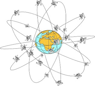
GPS is based on a system of 24 satellites moving in 6 elliptical orbits, each with 4 evenly distributed satellites and a 55 degree inclination to the equator at a height of 20200 km. The orbits are each offset by 60 degrees. The round trip time per satellite is 12 hours. Due to the rotation of the earth, only a certain number of satellites (max. 12) are visible above the visible horizon, relative to a fixed point on the earth. Optimal position determination is submit with 4 satellites from different directions on the visible horizon.
What is written here specifically to GPS, is transferable to all existing satellite navigation systems (GOLNASS / BAIDOU / GALILEO / NAVIC), the only difference, they are in orbits of different heights and operate on different carrier frequencies of the L-band (1-2 GHz).
2. GPS reference system
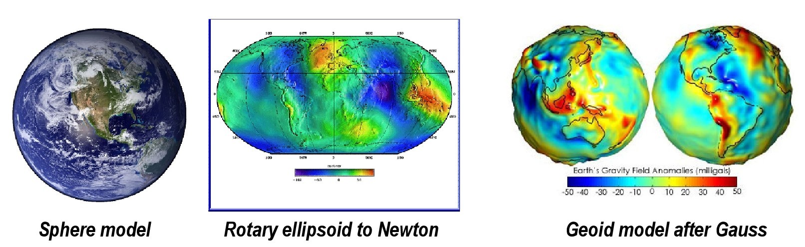
According to ancient ideas, the earth is a sphere, hence the Latin synonym Globus. However, this idealized sphere is not true to reality. Thanks to Isaac Newton, we know that the Earth is flattened at the poles because of its rotation and its equatorial gravitational field, and that it is slightly arched at the equator. This form of the Earth, known as the rotational ellipsoid, was much better suited than the spherical form for large-scale maps.
Gauss realized in the 19th century that the earth could not be a regular body due to the different mass distribution within the earth. He introduced the geoid as a better model, and defined it over the equipotential surface of the Earth's gravity field.
However, due to its difficult mathematical description, the geoid is not suitable for coordinate systems. Based on this fact, one resorts to the spherical model or the rotation ellipsoid.
Thereby were for ellipsoid models different variants of coordinate systems have been developed, which have now become established and represent the regions of the earth with different accuracy, such as the Bessel ellipsoid (Potsdam Datum), the International Ellipsoid (ED 50), the European Terrestial Reference System (ETRS89) and the World Geodetic System 1984 (WGS84). The differences between all these systems are small.
The WGS84 has established itself worldwide as a valid reference system as the basis for GPS. That is why all ECDIS systems and all systems using GPS are set to the date of the WGS 84 standards in shipping.
2.1 Coordinate systems in GPS
2.1.1 UTM Grid
The Geographical Grid describes as the most famous worldwide coordinate system the position on the earth, indicating latitude and longitude. The basis for this is the spherical model of the earth, which is covered with a length network of 360 ° and a latitudinal network of 180 °. The meridian of Greenwich, which runs through the observatory of Greenwich, has been the zero meridian since 1883.
The further longitudes and latitudes are run in same spaced. However, this distance is too inaccurate for position information, so that 1 ° was broken down into 60 arc minutes (') and 1 arc minute in 60 arc seconds ('').
However, the longitudes converge at the poles, which means that the distance between two degrees of longitude is different everywhere. As a result, a subdivision into degrees and minutes for distance measurement is only insufficiently possible.
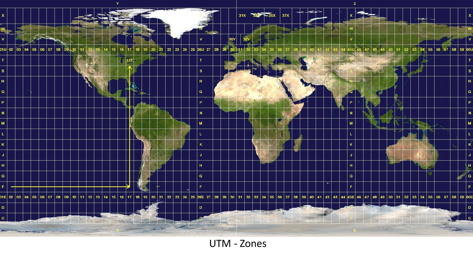
For the coordinate system to be used in the GPS, this is circumvented with the UTM grid (Universal Transverse Mercator projection), in which a rotation ellipsoid of the earth is assumed (mainly WGS84). The entire earth's surface is divided into 60 lengths and 20 width strips, which in turn are divided into 1200 smaller sections. UTM coordinate system and Gauss-Krüger coordinate system are similar and can be calculated with the same mapping equations. The main difference is that UTM coordinates refer to WGS84 and UTM zones are projected onto a plane in 6° long strips of length, creating a rectangle.
While the Gauss-Krüger projection refers to the Bessel or Krassowski ellipsoid and uses 3 ° wide longitudinal stripes. However, the described coordinate systems are only fixedly referred to the earth's surface so that only points can be described on it.
2.1.2 ECEF - Coordinate System
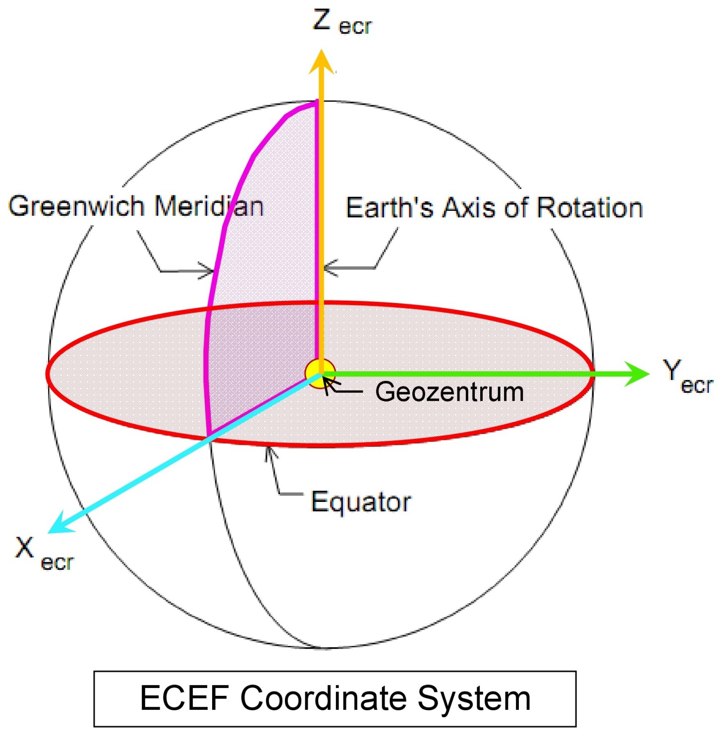
But we have to do it with satellite navigation, used as a location systems and the satellites are important reference points for positioning. However, since these are in orbits above the Earth, a coordinate system is required, which can represent both points on and above the Earth , To do this, the GPS uses the ECEF (Earth Centered-Earth Fixed Coordinate System) coordinate system. With the following definition:
This coordinate system is dextrorotatory and rotates with the earth. With it, all points on the earth's surface and above, i.e. satellites and airplanes can be represented
2.1.3 ECI – Coordinate system
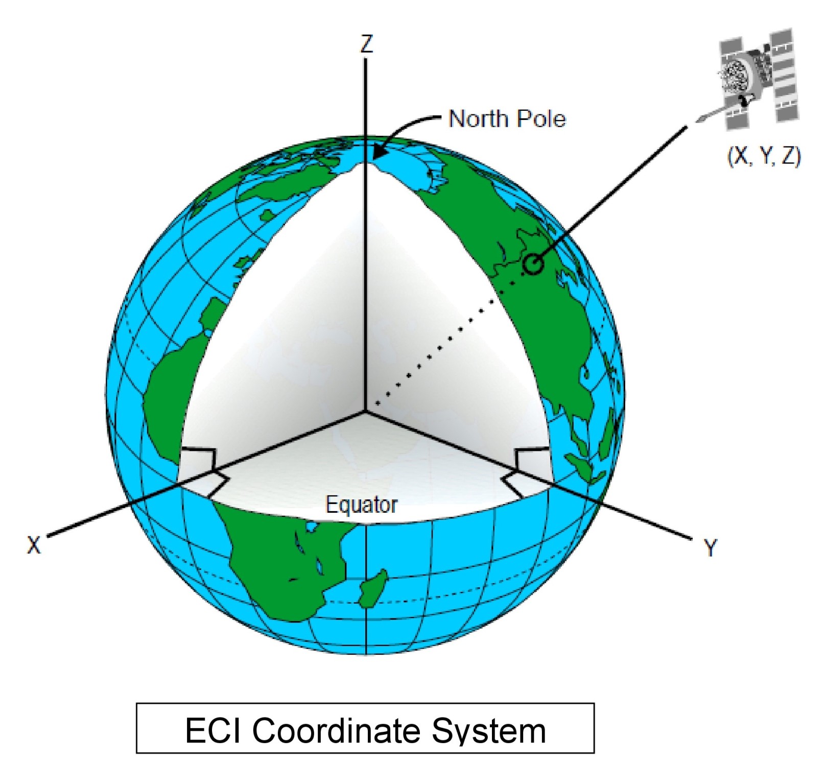
ue to the irregularities in the earth's movement, the ECEF coordinate system is not inertial, especially it has to be remarked to the precession movement of the earth. That is due to the orbit of the earth around the sun, the axis of rotation (Z-axis) of the earth is not spatially fixed. For this reason, it was agreed to refer the Z-axis of the ECEF coordinate system to the position of the earth on 01.01.2000 and thus to create a space-stable inertial system. This system is referred to as the ECI (Earth Centered Inertial Coordinate System) coordinate system
Inertial = when every force-free body remains at rest relative to this frame of reference, or moves uniformly (unaccelerated) and in a straight line.
Inertial System = A system of reference in physics is called the inertial system, when every force-free body remains at rest relative to this frame of reference or moves uniformly and in a straight line
So we recognize that GPS consists of several reference systems. Therefore, it is also necessary that the WGS4 reference date on board be used for the nautical systems.
On the altitude determination in GPS is deliberately not entered by me, because it plays no role in the seafaring. It is primarily used for GPS ashore for elevation.
3. Segments of the GPS
GPS consists of three segments:
3.1 Space segment (satellites)
It is important to know that in the space segment must take into consideration that at least 4 satellites must be visible from any point in the world, which plays an important role in the selection of the satellite constellation. This is achieved by:
• Big orbit heights (19000 km and more)
• Inclination of the orbit (55°)
• Equal distribution of satellites on the orbit (4 satellites)
• Symmetry of the satellite orbits (6 with 60° offset orbits)
The description of the satellite orbits is based on the laws of Kepler's laws, that is, on the same principles that describe the movement of the planets around the Sun, discovered by Johannes Kepler (1571-1630), German mathematician, astronomer, optician and theologian
a) All satellites move in elliptical orbits around the earth, where in their one focal point lies the Earth's geocenter.
b) The connecting line between the earth's geocenter and any satellite sweeps the same area at equal time intervals.
c) The squares of the orbital periods of the satellites are proportional to the cube of the large axis of the orbital ellipse.
Gravity and Kepler's laws form the basis of mathematical algorithms for determining the position of satellites at any time point.
This should be sufficient as basic knowledge and basis of understanding.
3.2 Control segment (ground station))
The task is to calculate the various navigation data to determine the satellite positions in real time.
The following tasks are to be exercised
a) Observing the satellite movements and calculating the orbit data
b) Monitoring and synchronization of satellite clocks
c) Transmission and relay of the exact orbit data and predictions about the behavior of the watch by means of radio contact to the users
For this purpose, stationary monitoring GPS stations are operated for system error corrections, the required calculations for ephemeris and satellite orbits are carried out in a master control station (MCS) and combined in navigation messages.
3.3. User segment (military and civil user))
That means the various brands of GPS receivers aboard which are in use by the users.
It must always be reminded that GPS is in the hands of US forces. It should be noted that there are two different categories of accuracy.
• Standard Positioning Service (SPS)
• Precise Positioning Service (PPS)
which are provided for the different users. PPS is mainly reserved for the military and other government departments.
4. Operation of GPS
4.1 Position determination
Position determinations of satellite-based positioning systems are based on the principle of transit time measurement of electromagnetic waves in the high-frequency range (L-band, f = 1-2 GHz, λ = 30 -50 cm). The exchange of information between the MCS and the satellite takes place in the S band (f = 2-4 GHz, λ = 7.5 -15 cm).
4.1.1. Small wave theory
Electromagnetic waves are periodic changes in the state of the electromagnetic field. The electrical and magnetic fields are composed of state vectors.
Basically, harmonic waves are used in GPS, which are characterized in that a temporal and spatial periodic deflection takes place from the rest position. It would go too far now to elaborate a theoretical treatise on Maxwell's equations describing the phenomenon of electromagnetism, how electric and magnetic fields are related. It is important to know that this waveform can be represented mathematically as a simple sinusoidal form. For a better understanding, the following explanations:
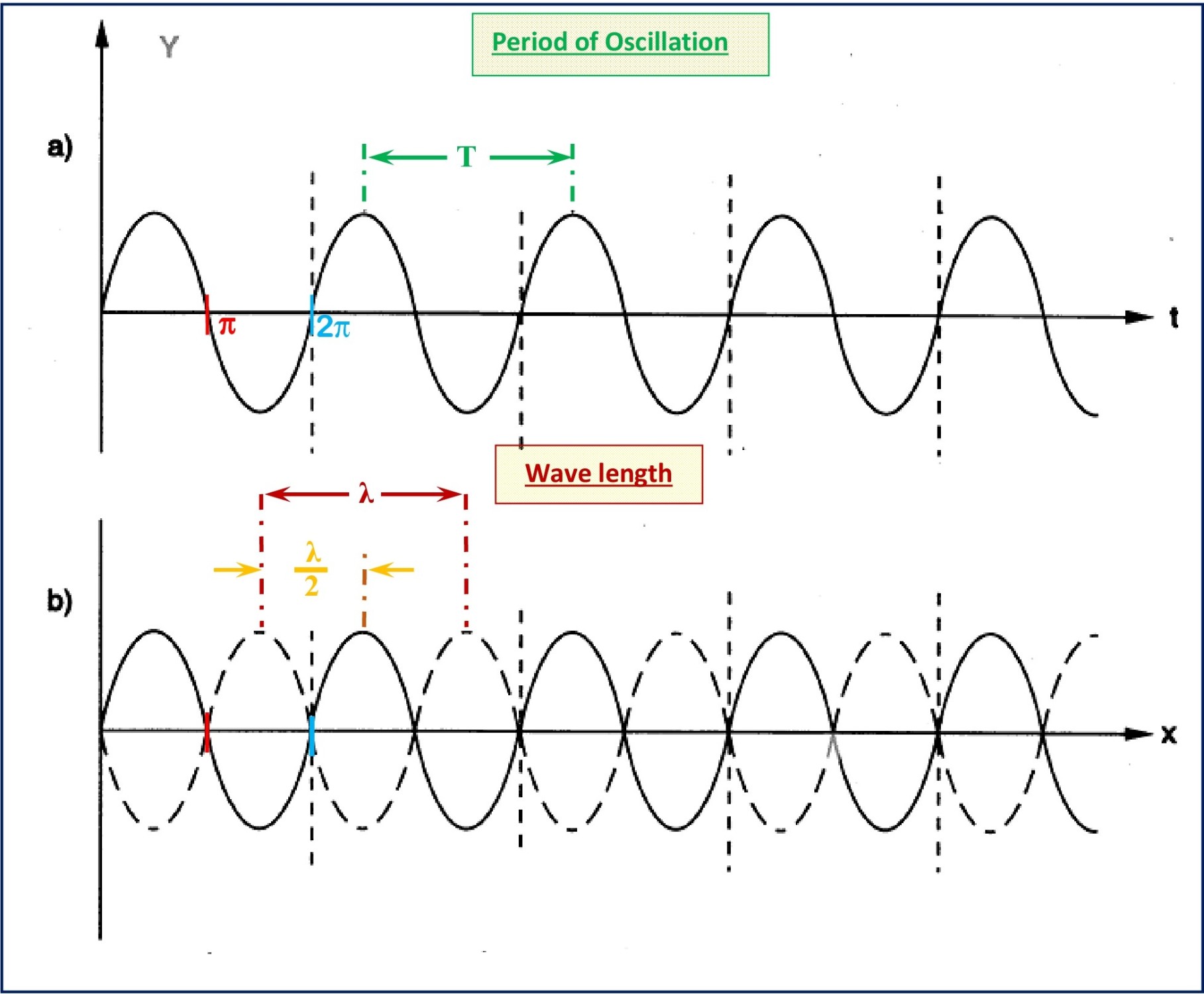
a) If an electromagnetic field is observed at a constant location, so will be the duration of oscillation T as the time distance between two points of the same oscillation state called. The frequency is then given by f = 1 / T.
b) Assuming a fixed time point, the electromagnetic field changes periodically with increasing distance from the transmitter and the spatial distance between two points of the same phase is defined as wavelength λ
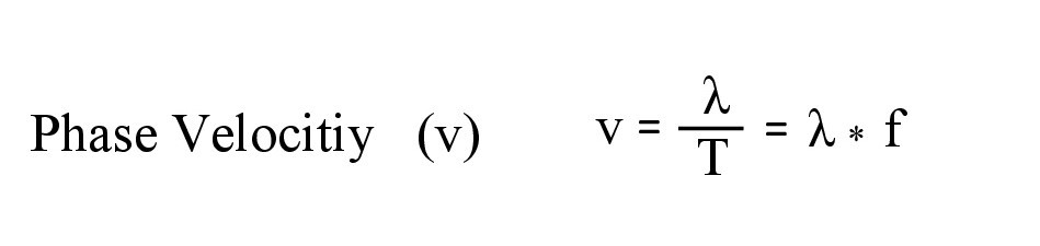
During the time T, the wave shifts by λ, so the propagation velocity of the electromagnetic wave in space is defined as the phase velocity v as follows:
In vacuum, electromagnetic waves propagate at the speed of light. However, in the Earth's atmosphere and on Earth, part of the electrical energy is converted into heat by friction, resulting in damping of the wave. This attenuation is caused by the atmosphere gases in the atmosphere, precipitation particles (rain), reflection on the earth's surface or at objects including multipath propagation. Also, in electromagnetic waves, similar to light, a refraction occurs, which is mainly caused by the decrease of the atmospheric density in height. In addition, the effects of diffraction on objects and the phase delays due to the atmosphere should not go unmentioned.
The behavior of electromagnetic waves in the earth's atmosphere is frequency-dependent. High frequencies are better suited for signal transmission. That' why, only frequency bands in the microwave range are used for data transmission with GPS from the broad spectrum of electromagnetic wave.
4.2. Frequencies in the GPS
Position determination in GPS is based on the measured signal propagation time of the signals emitted by the satellites. Satellites send permanent signals on two frequencies:
The following frequencies are used for GPS.
f1 = 1575.42 MHz (called L1), with the use of the C / A code (Coarse / Aquisition) and
f2 = 1227.6 MHz (called L2), using the P / Y code (Precision / Encrypted).
Whereas L1 is provided for civilian use and L2 is primarily reserved for military use. Why 2 frequencies?
a) The higher the frequency, the lower the delay of the signal in vacuum
b) At frequencies of <100 MHz, the ionospheric delay is particularly high
c) At frequencies of> 10 GHz, the tropospheric damping is particularly large
d) The emission of two frequencies allows the determination of the ionospheric delay
e) Only the frequency range of the L-band provides the large bandwidths needed to use the PRN codes (Pseudo-Random-Noise Code)
4.3. Physical and technical basics
This chapter is not about producing small Einsteins, but rather about conveying simplified basic physical and technical knowledge in order to understand the GPS technical system. Nautical officers, as users of GPS, should also have knowledge of the basis on which GPS works and that it has as a technical system physical and technical limits of use. This should be known. Because they mean use restrictions. These chapters require a basic physical and mathematical understanding and basic knowledge of wave theory. I point out that I am referring exclusively to the maritime application of GPS.
4.3.1. Time dilation
The fundamental frequency of the satellite oscillator is f0 = 10.23 MHz (λ = 29.3 m). From it all frequencies are derived.
When setting the fundamental frequency, it is necessary to incorporate relativistic influences of the special theory of relativity (Albert Einstein, 1905).
For this it is required to consider two types of time dilation:
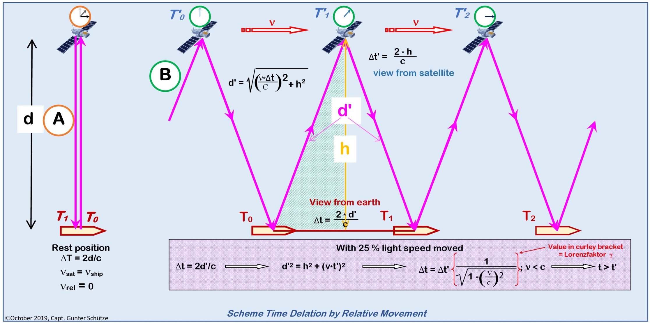
a) Time dilation by movement tells:
"That all internal processes of a physical system are elapsing slower relative to the observer if this system moves relative to the observer."
What does that mean?
This means that watches that move relative to the observer, go slower than his own. This effect is stronger the greater the relative velocity.
In other words, clocks in fast-moving reference systems are slower than those in stationary reference systems.
In terms of GPS, this means that the clocks in the satellites are slower than the clocks in the receivers on the ground.
b) Gravitative time dilation tells:
"That a watch, like any other process, runs slower in a stronger gravitational field than in a weaker one."
In this way time passes in a distant, approximately gravitational free space faster than on the earth's surface. More precise, everybody opposite to the gravitational field resting observer measures a longer or shorter elapse time of events which are triggered in an identical manner in and out of the gravitational field. Different to time dilation by relative motion, is the gravitational time dilation not mutually. While the upper observer in the gravitational field sees the time of the lower observer goes slower, the lower observer sees the time of the upper observer goes correspondingly faster.
In terms of GPS, this means that the clocks in the satellites go faster than the clocks in the receivers on the ground.
If one summarizes both effects and considers the frequency shift instead of the time offset, the result for the GPS system is that the frequency of the satellite clocks is of the factor 4.5 * 10-10 Hz higher than that of a reference clock on Earth's surface. To compensate for this effect and assume a fundamental frequency of 10.23 MHz, the frequencies of the satellite clocks are set to a value of
f = 10.22999999545 MHz
4.3.2. Phase Modulation
Signals with simple harmonic oscillation hold the danger of
Unwanted third-party-use, due to the free access
Signal ambiguity caused by measurement of phasing position in the range of one wavelength, which doesn't allows a current satellite position for the user.
By phase modulation of the signals, the problems mentioned can be avoided.
To that for f1 and f2 will used so-called pseudo-random sequences, also called pseudo-random noise codes (PRN code).
In order to make the signal of a particular satellite recognizable to the receiver and to transmit the navigation message, the signals are modulated in several steps, in which the phases of the carrier frequencies f1 and f2 in accordance with pseudorandom sequences of the values +1 and -1 (PRN Sequences) are changed. For a random sequence, each element takes the values +1 and -1 with the same probability. For a pseudo-random sequence, the sequence of elements will repeat the period of the sequence after a certain time. The values +1 and -1 in the case of the GPS signals are functional values of a stair function of the satellite time T (also known as the Heaviside function, named after the British mathematician and physicist Heaviside, see F(T) in the adjacent diagram) and cause the following:
+1, the signal remains unchanged.
-1 causes a phase shift about 180 °.
In order to be able to exclude interferences of the signals and assign them clearly to the satellite, the selection of the specific PRN sequences takes place so that they do not correlate with each other. At the same time, the frequencies L1 and L2 are coded differently to restrict civilian use. In the following subchapter more.
4.3.3. GPS Signal Coding
In my explanation, I confine myself to the principle of coding, the signal L1 accessible for civilian use, since the coding procedure for L2 is based on exactly the same principles. With the difference that for L2 only the cosine wave is modulated and the carrier frequency is generated by f1 = 120 * f0.
In order to obtain the carrier frequency f1, it must be derived from the fundamental frequency; f1 = 154 * f0. By phase shift by 90 ° then another carrier is generated, so that a sine wave and a cosine wave of frequency f1 are present. Subsequently, the two waves are modulated differently and the addition of the modulated waves is transmitted.
The modulation clock (modulation code) indicates in which cycle the stair function of the PRN sequence changes or retains its value. The period is the length of the repeating sequence, so that the product of the modulation clock and period is results the number of elements +1 and -1 within a sequence. The ratio carrier frequency to the modulation clock determines how many waves of a wave train are modulated. For example, in the case of the C / A code, this is every 1540th wave. The Multiplication with the wavelength of the L1 signal λ1 = 0.19 m provides the 'wavelength of the code'.
The data code modulation, which is the same for both waves, follows the modulation with the PRN sequences. In order to guarantee real-time satellite positioning, the required parameters and additional information of the satellites must be available. This is achieved by the fact that the signal with a further phase modulation, packs data for a navigation message and transmits with the signal. The message itself is a 30 second sequence of +/- 1 in the 50 Hz cycle.
4.3.4. Runtime Measurement
Runtime measurement is a method of indirect distance or velocity measurement by measuring that time which a signal requires to traverse the measuring distance
In this method, the time of a signal emitted by a transmitter is measured until it reaches a known location.
The transit time measurement in GPS is a one-way measurement. In order to obtain a position, signals from several transmitters are required, in the case of GPS, the electromagnetic waves of several satellites (at least 4).
Due to their different distances to a ship, different measured transit time’s result, which are multiplied by the speed of light (c). Their lines converge in the position of the ship. The application of the 4th satellite for transit time measurement serves to determine the receiver watch error.
It is important that the clocks of the transmitters and the ship are synchronized and display the same time. The GPS time is a globally uniform atomic clocked time without a leap second, as opposed to UTC, where this leap second is inserted to keep UTC in agreement with Earth's rotation. Because of this, GPS time and UTC differ, which means GPS time is currently 18 seconds ahead of UTC.
4.4. Position Determination
GPS positioning is based on the signal being received by at least 3 satellites.
It is not based on the true distances to the satellites, but so - called pseudo - distances, which come about as follows:
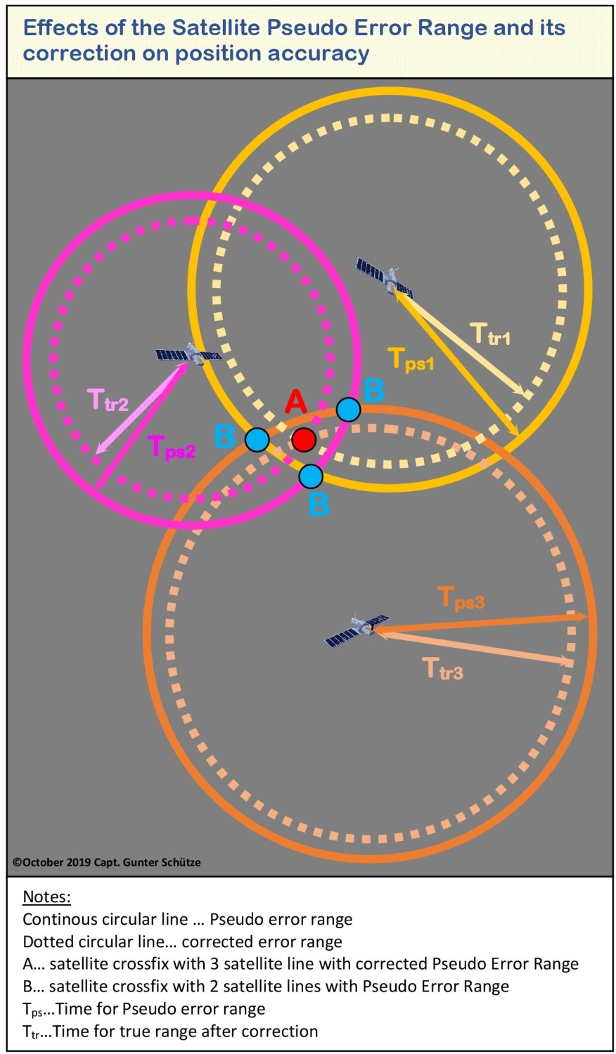
The modulated signals are used for position determination. Thus, if a satellite is in the range of the GPS receiver, its signal transit time Δt is determined by generating an identical signal and determining the phase shift. By multiplying by the speed of light (c), the pseudo-distance from the satellite can be determined.

It is thereby assumed that the different clocks are not synchronized. Based on the GPS system time, one starts from a reference time, which is the deviations of user time (receiver) to system time (tu) and satellite time to system time (ts). Thus it can be seen that the pseudo-distance is an error caused by time differences, so that

for the actual distance of the user from the satellite is valid.
As the intellectual connection, it should be pointed out that this method of position determination in the broader sense has a similarity with hyperbola radio location procedure.
4.5. Speed Determination
The speed of vessels in the GPS is determined by the Doppler Effect.
4.5.1. Doppler Effect
The Doppler Effect is named after the Austrian mathematician and physicist Christian Doppler, who in 1842 hypothesized that the colored light of stars is due to their change in distance during light emission. However, this could not be scientifically maintained. However, in 1845 with the commissioning of the railway succeeded in experimental proof of the acoustic Doppler Effect.
The Doppler Effect is based on the change in signal propagation time. It is referred to as the time compression or stretching of a signal with changes in the distance between transmitter and receiver during the duration of the signal. This purely kinematic (resulting from the motion) effect occurs with all signals that propagate at a certain speed, usually the speed of light or the sound velocity. When propagation in a medium, such as water, its state of motion must be considered.
That means nothing else than:
If an object in motion is approaches an object at rest, then the signal waves are compressed, with the effect that the wavelength (λ) is shortened, resulting in a frequency change to higher frequencies (f). Acoustically, it is noticeable that the pitch increases during the approaching phase.
If the moving object passes the resting object and moves away, the opposite occurs. The signal waves are stretched, the wavelength will thus longer and thus the frequency comes lower, which is acoustically in progressively lower tones

These frequency changes are referred to as Doppler frequency shift.
Even if both objects are in motion, this principle forms the basis of the velocity determination, since the same effects occur on approaching and to move away motion, taking into account the motion parameters of both objects, so long the two objects have different motion velocity (the relative speed vector must be > 0).
4.6. Course determination in the GPS
The course calculation in the GPS is based on the determination of the distance traveled, that is. It is an analysis of the direction of movement of ship positions in past, which are connected by straight lines whose direction is shown as a two-dimensional course vector in 360 degree representation, north stabilized. In a figurative sense, this can be compared with the radar representation in the "Past Track" mode. The accuracy of the course value is depends from accuracy of the receiver and the time interval of the position determination. To do this, the GPS receiver must be in motion. This also explains why for ships at anchor while turning around the anchor the course and speed determination is jumpy.
The position update is performed every 1 second in the standard procedure and every 0.1 second at the maximum update rate.
4.7. Selected Availability and Anti-Spoofing
A short insight into the possibilities of influencing the accuracy of GPS and preventing spoofing against GPS.
4.7.1. Selective Availability (SA)
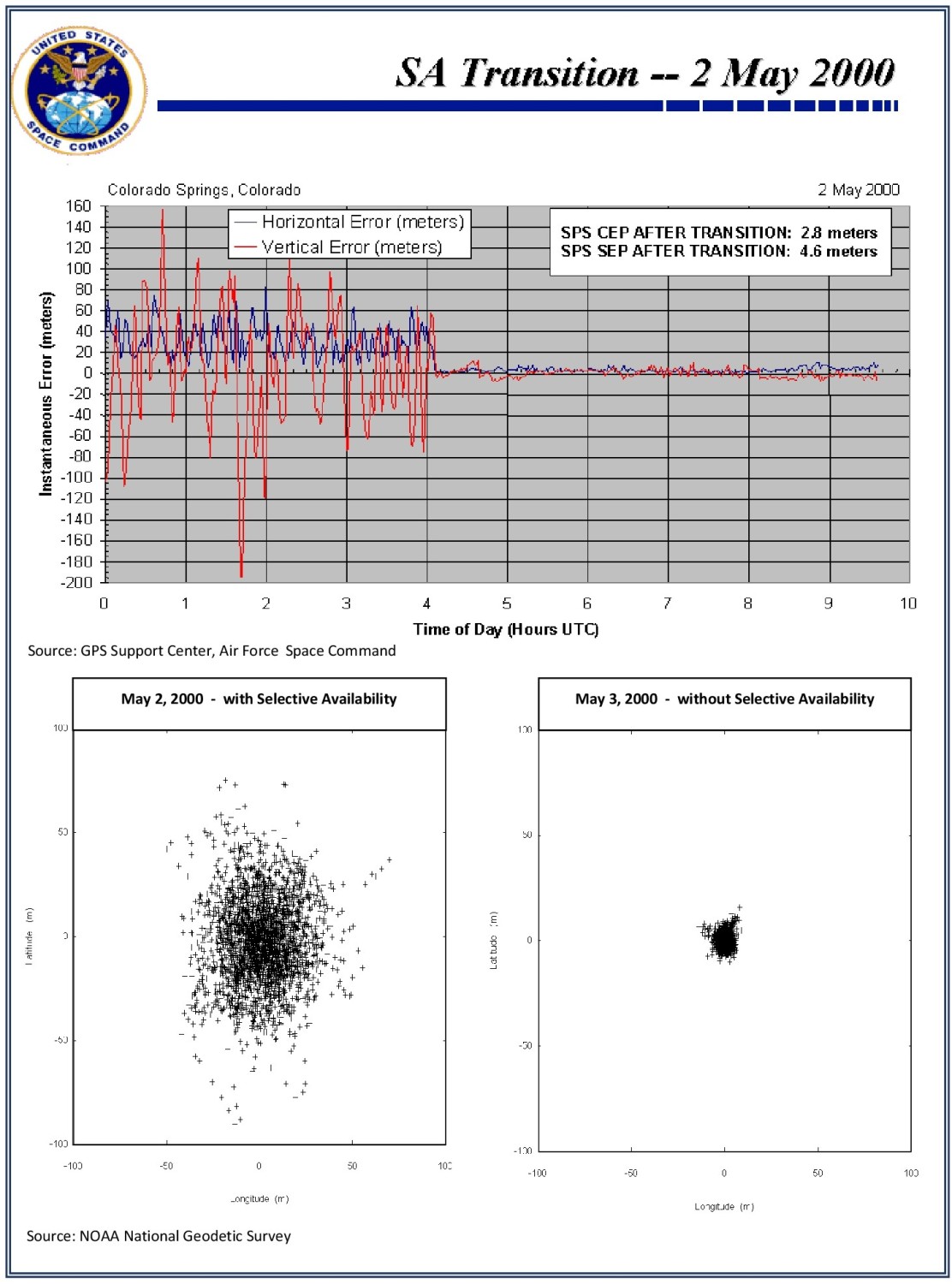
he accuracy of GPS available to the user is at the operator's discretion with the Selected Availability (SA) tool. There have been discussions over and over again in the past, because the accuracy differences are considerable. With SA: 100 -150 m and without SA: 5 - 10 m. They are caused by artificial falsification of the satellite orbits and by artificially created receiver noise of the carrier signal. SA was switched off in May 2000. The effects can also be seen in the left graphic.
AS is usable to the L1 and L2 frequency.
4.7.2. Anti-Spoofing (A-S)
Anti-spoofing is established to prevent that transmitted signals can be influenced by false signals and thus will receiving incorrect information from the receivers which limit or even render impossible the function of GPS.
For this purpose, the P-code (Precise Code) is additionally encrypted with a Y-code, referred to as P / Y code. This ensures that for unauthorized users, ie the public, only the C / A coded part (Coarse / Aquisition - Civilian Access Code) of the L1 frequency can be used.
Authorized users of the P / Y code, armed forces and authorized authorities typically have dual frequency receivers that can receive L1 and L2 frequencies that are automatically corrected via a dedicated receive module and operate with high accuracy.
It must always be aware that GPS is a military system under the control of the US Forces. That means that SA and A-S can be activated at any time for the L1 frequency resulting in limited civilian use.
In the past, some regions of the world, e.g. Black Sea and Northern Norway, have reported massive disruptions of GPS usage allegedly due to spoofing attacks. I see these reports critically, as also technical and physical error influences, the function can disturb massively. But more on that later.
5. DGPS (Differential Global Positioning System)
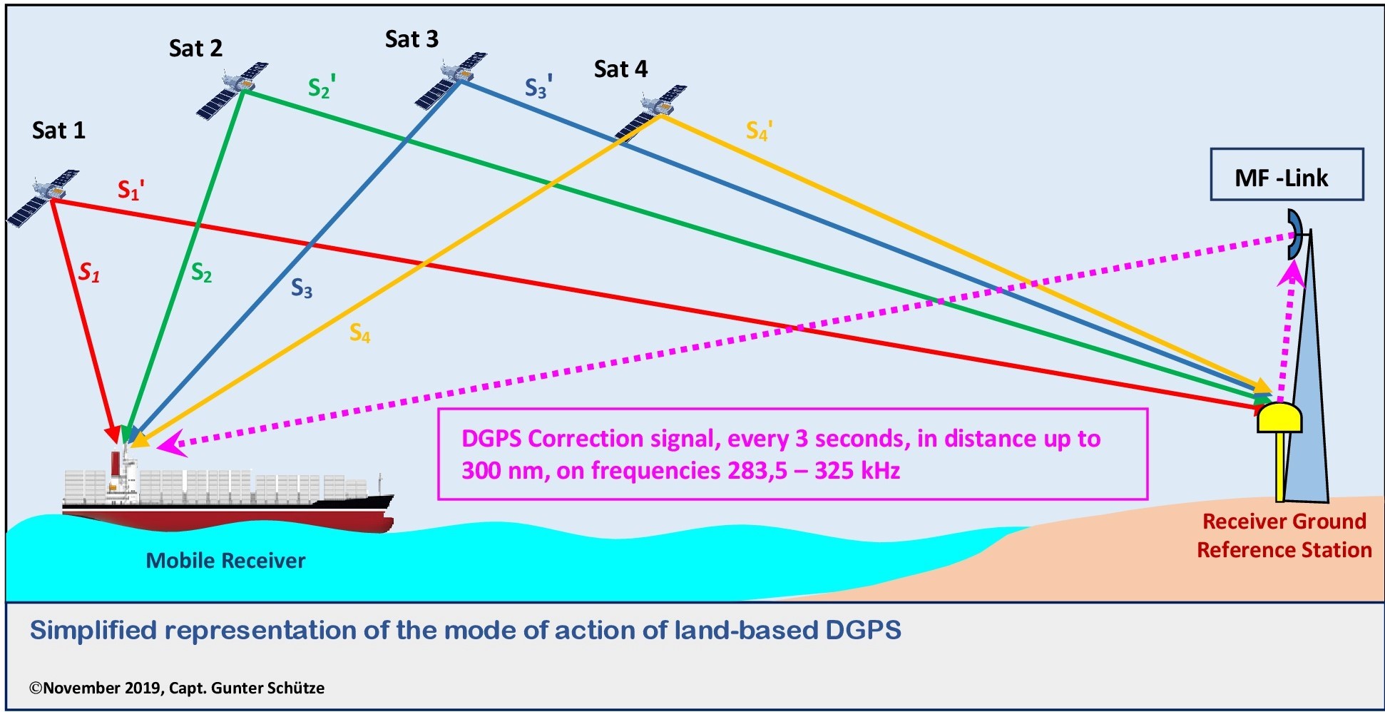
DGPS is a system that also works on the basis of transit time measurement. It is founded on stationary antennas that are installed as reference stations on land. Their position has been determined by classical surveying methods, which ensures a high accuracy of the position. DGPS has the task to correct the existing error inaccuracies of GNSS (Global Navigation Satellite System). DGPS is not limited to GPS, but for GNSS, so all existing satellite navigation systems available.
The method makes use of the fact that the actual signal propagation times can be determined from the deviation of the actual position and the received position. The difference between the theoretical and the actual signal propagation time is transmitted to the DGPS receivers in the respective region. DGPS receivers on board correct this difference and thus increase the accuracy of the position determination. The associated accuracy depends on the distance of the receiver from the reference station on land. Accuracies of approx. 0.5 m to 2.5 m are possible.
It is noteworthy that, in addition to the onshore stationary regional DGPS reference stations, which is only regionally usable, there is also a satellite-based DGPS system, which enables the worldwide use of DGPS.
It is based on geostationary satellites orbiting Earth at 36000 km altitude, always maintaining their same position to Earth. It is referred to as SBAS (Satellite Based Augmentation System) and also serves to increase the accuracy in determining the position of GNSS.
There are currently four systems active and two more systems under construction, but these are currently mainly used in flight navigation.
Epilogue
The purpose of this paper is primarily to provide nautical cadets, students and officers with basic knowledge about GPS as currently the most commonly used satellite navigation system. I have the view that the user must be able to know technical and physical fundamentals. The practice on board has shown that only fragmentary knowledge is available.
I hope this work is a clearly arranged form a way given to navigators’ basic knowledge to hand.
In the second part I will deal more intensively with occurring technical and physical errors, which are unavoidable with GPS as a technical system, which is used on the basis of the wave theory. This should also help to not immediately classify any irregularity in the operation of GPS as a spoofing attack.
© Copyright November 2019, Capt. Gunter Schütze. Replication or redistribution in whole or in part is expressly prohibited without the prior written consent by Capt. M.Eng. Gunter Schütze
Of course, as a Nautical Specialist, I also deal with the international discussion on the advantages and disadvantages of satellite-based navigation, e-navigation and conventional terrestrial and astronomical navigation.
Unfortunately, in the analysis of marine casualties, one gets the impression that the use of different navigation procedures proves that satellite navigation via GPS is given absolute priority and inexplicably the other types of navigation are neglected to the utmost degree.
Why is that so?
Is it due to the convenience and apparent simplicity that GPS Navigation suggests?
Is it due to the greater effort required by conventional navigation methods for exact position determination?
Is there any lack of knowledge about these conventional procedures?
Is it due to the lack of practice to use conventional navigation techniques?
Is it due to today's insufficient technical equipment standards for conventional navigation methods?
Let us first turn to the navigation via GPS navigation
GPS today seems to be the panacea for position determination in shipping. It is easy to handle, is automatically transmitted via the corresponding interfaces (NMEA 0183) to all possible technical components of integrated bridge systems and is apparently easy to use on ECDIS. COG, SOG, drift, wind, continued position update are represented by the data provided by GPS by satellite, to computer. Accuracies in the position of up to 3 m are the non-plus ultra of GPS navigation and accessible via DGPS. It is interesting that the GPS data in all existing nautical and technical systems on board, such as GPS receivers, echo sounders, logs, gyros compass, radar systems, ECDIS, NautoConning, control systems, satellite C, VHF, HF, AIS, VDRs, to limit it to bridge equipment, find their entrance.
GPS is in the broader sense a passive system.
In contrast to the EPIRB's, which are an active system and have nothing to do with GPS, but are linked to COSPAS / SARSAT within the worldwide GMDSS.
GPS offers interesting positive usability, especially when it comes to accuracy, such as maneuvering in confined spaces with existing electronic tools / menus, e.g. predicted path and nauto-conning displays, e.g. docking) provide helpful support for the ship's command. However, they are only tools which should always be kept in mind and they do not relieve the ships command team of visually visual monitoring of maneuvers and ship movement from the bridge and bridge wings.
Experience has shown that many navigation officers do not really have deeper knowledge of GPS and that such a technical system it also has sources of error due to physical and technical causes.
For this reason, for a better understanding a brief consideration to the structure of GPS, its principles of action as well as technical and physical fundamentals, which should be indispensable for the user.
Location and Navigation -What are the differences?
Locating here means the 'determination of the geographic latitude and longitude of a place on the earth's surface with the help of various navigational procedures, how terrestrial navigation with land marks or celestial navigation with stars or planets or radio location'.
Navigation is the task and the process of moving a vehicle on a predetermined route from a starting point (departure) to a defined end point (destination)
1. Construction of GPS
GPS is based on a system of 24 satellites moving in 6 elliptical orbits, each with 4 evenly distributed satellites and a 55 degree inclination to the equator at a height of 20200 km. The orbits are each offset by 60 degrees. The round trip time per satellite is 12 hours. Due to the rotation of the earth, only a certain number of satellites (max. 12) are visible above the visible horizon, relative to a fixed point on the earth. Optimal position determination is submit with 4 satellites from different directions on the visible horizon.
What is written here specifically to GPS, is transferable to all existing satellite navigation systems (GOLNASS / BAIDOU / GALILEO / NAVIC), the only difference, they are in orbits of different heights and operate on different carrier frequencies of the L-band (1-2 GHz).
2. GPS reference system
According to ancient ideas, the earth is a sphere, hence the Latin synonym Globus. However, this idealized sphere is not true to reality. Thanks to Isaac Newton, we know that the Earth is flattened at the poles because of its rotation and its equatorial gravitational field, and that it is slightly arched at the equator. This form of the Earth, known as the rotational ellipsoid, was much better suited than the spherical form for large-scale maps.
Gauss realized in the 19th century that the earth could not be a regular body due to the different mass distribution within the earth. He introduced the geoid as a better model, and defined it over the equipotential surface of the Earth's gravity field.
However, due to its difficult mathematical description, the geoid is not suitable for coordinate systems. Based on this fact, one resorts to the spherical model or the rotation ellipsoid.
Thereby were for ellipsoid models different variants of coordinate systems have been developed, which have now become established and represent the regions of the earth with different accuracy, such as the Bessel ellipsoid (Potsdam Datum), the International Ellipsoid (ED 50), the European Terrestial Reference System (ETRS89) and the World Geodetic System 1984 (WGS84). The differences between all these systems are small.
The WGS84 has established itself worldwide as a valid reference system as the basis for GPS. That is why all ECDIS systems and all systems using GPS are set to the date of the WGS 84 standards in shipping.
2.1 Coordinate systems in GPS
2.1.1 UTM Grid
The Geographical Grid describes as the most famous worldwide coordinate system the position on the earth, indicating latitude and longitude. The basis for this is the spherical model of the earth, which is covered with a length network of 360 ° and a latitudinal network of 180 °. The meridian of Greenwich, which runs through the observatory of Greenwich, has been the zero meridian since 1883.
The further longitudes and latitudes are run in same spaced. However, this distance is too inaccurate for position information, so that 1 ° was broken down into 60 arc minutes (') and 1 arc minute in 60 arc seconds ('').
However, the longitudes converge at the poles, which means that the distance between two degrees of longitude is different everywhere. As a result, a subdivision into degrees and minutes for distance measurement is only insufficiently possible.
For the coordinate system to be used in the GPS, this is circumvented with the UTM grid (Universal Transverse Mercator projection), in which a rotation ellipsoid of the earth is assumed (mainly WGS84). The entire earth's surface is divided into 60 lengths and 20 width strips, which in turn are divided into 1200 smaller sections. UTM coordinate system and Gauss-Krüger coordinate system are similar and can be calculated with the same mapping equations. The main difference is that UTM coordinates refer to WGS84 and UTM zones are projected onto a plane in 6° long strips of length, creating a rectangle.
While the Gauss-Krüger projection refers to the Bessel or Krassowski ellipsoid and uses 3 ° wide longitudinal stripes. However, the described coordinate systems are only fixedly referred to the earth's surface so that only points can be described on it.
2.1.2 ECEF - Coordinate System
But we have to do it with satellite navigation, used as a location systems and the satellites are important reference points for positioning. However, since these are in orbits above the Earth, a coordinate system is required, which can represent both points on and above the Earth , To do this, the GPS uses the ECEF (Earth Centered-Earth Fixed Coordinate System) coordinate system. With the following definition:
This coordinate system is dextrorotatory and rotates with the earth. With it, all points on the earth's surface and above, i.e. satellites and airplanes can be represented
2.1.3 ECI – Coordinate system
ue to the irregularities in the earth's movement, the ECEF coordinate system is not inertial, especially it has to be remarked to the precession movement of the earth. That is due to the orbit of the earth around the sun, the axis of rotation (Z-axis) of the earth is not spatially fixed. For this reason, it was agreed to refer the Z-axis of the ECEF coordinate system to the position of the earth on 01.01.2000 and thus to create a space-stable inertial system. This system is referred to as the ECI (Earth Centered Inertial Coordinate System) coordinate system
Inertial = when every force-free body remains at rest relative to this frame of reference, or moves uniformly (unaccelerated) and in a straight line.
Inertial System = A system of reference in physics is called the inertial system, when every force-free body remains at rest relative to this frame of reference or moves uniformly and in a straight line
So we recognize that GPS consists of several reference systems. Therefore, it is also necessary that the WGS4 reference date on board be used for the nautical systems.
On the altitude determination in GPS is deliberately not entered by me, because it plays no role in the seafaring. It is primarily used for GPS ashore for elevation.
3. Segments of the GPS
GPS consists of three segments:
3.1 Space segment (satellites)
It is important to know that in the space segment must take into consideration that at least 4 satellites must be visible from any point in the world, which plays an important role in the selection of the satellite constellation. This is achieved by:
• Big orbit heights (19000 km and more)
• Inclination of the orbit (55°)
• Equal distribution of satellites on the orbit (4 satellites)
• Symmetry of the satellite orbits (6 with 60° offset orbits)
The description of the satellite orbits is based on the laws of Kepler's laws, that is, on the same principles that describe the movement of the planets around the Sun, discovered by Johannes Kepler (1571-1630), German mathematician, astronomer, optician and theologian
a) All satellites move in elliptical orbits around the earth, where in their one focal point lies the Earth's geocenter.
b) The connecting line between the earth's geocenter and any satellite sweeps the same area at equal time intervals.
c) The squares of the orbital periods of the satellites are proportional to the cube of the large axis of the orbital ellipse.
Gravity and Kepler's laws form the basis of mathematical algorithms for determining the position of satellites at any time point.
This should be sufficient as basic knowledge and basis of understanding.
3.2 Control segment (ground station))
The task is to calculate the various navigation data to determine the satellite positions in real time.
The following tasks are to be exercised
a) Observing the satellite movements and calculating the orbit data
b) Monitoring and synchronization of satellite clocks
c) Transmission and relay of the exact orbit data and predictions about the behavior of the watch by means of radio contact to the users
For this purpose, stationary monitoring GPS stations are operated for system error corrections, the required calculations for ephemeris and satellite orbits are carried out in a master control station (MCS) and combined in navigation messages.
3.3. User segment (military and civil user))
That means the various brands of GPS receivers aboard which are in use by the users.
It must always be reminded that GPS is in the hands of US forces. It should be noted that there are two different categories of accuracy.
• Standard Positioning Service (SPS)
• Precise Positioning Service (PPS)
which are provided for the different users. PPS is mainly reserved for the military and other government departments.
4. Operation of GPS
4.1 Position determination
Position determinations of satellite-based positioning systems are based on the principle of transit time measurement of electromagnetic waves in the high-frequency range (L-band, f = 1-2 GHz, λ = 30 -50 cm). The exchange of information between the MCS and the satellite takes place in the S band (f = 2-4 GHz, λ = 7.5 -15 cm).
4.1.1. Small wave theory
Electromagnetic waves are periodic changes in the state of the electromagnetic field. The electrical and magnetic fields are composed of state vectors.
Basically, harmonic waves are used in GPS, which are characterized in that a temporal and spatial periodic deflection takes place from the rest position. It would go too far now to elaborate a theoretical treatise on Maxwell's equations describing the phenomenon of electromagnetism, how electric and magnetic fields are related. It is important to know that this waveform can be represented mathematically as a simple sinusoidal form. For a better understanding, the following explanations:
a) If an electromagnetic field is observed at a constant location, so will be the duration of oscillation T as the time distance between two points of the same oscillation state called. The frequency is then given by f = 1 / T.
b) Assuming a fixed time point, the electromagnetic field changes periodically with increasing distance from the transmitter and the spatial distance between two points of the same phase is defined as wavelength λ
During the time T, the wave shifts by λ, so the propagation velocity of the electromagnetic wave in space is defined as the phase velocity v as follows:
In vacuum, electromagnetic waves propagate at the speed of light. However, in the Earth's atmosphere and on Earth, part of the electrical energy is converted into heat by friction, resulting in damping of the wave. This attenuation is caused by the atmosphere gases in the atmosphere, precipitation particles (rain), reflection on the earth's surface or at objects including multipath propagation. Also, in electromagnetic waves, similar to light, a refraction occurs, which is mainly caused by the decrease of the atmospheric density in height. In addition, the effects of diffraction on objects and the phase delays due to the atmosphere should not go unmentioned.
The behavior of electromagnetic waves in the earth's atmosphere is frequency-dependent. High frequencies are better suited for signal transmission. That' why, only frequency bands in the microwave range are used for data transmission with GPS from the broad spectrum of electromagnetic wave.
4.2. Frequencies in the GPS
Position determination in GPS is based on the measured signal propagation time of the signals emitted by the satellites. Satellites send permanent signals on two frequencies:
The following frequencies are used for GPS.
f1 = 1575.42 MHz (called L1), with the use of the C / A code (Coarse / Aquisition) and
f2 = 1227.6 MHz (called L2), using the P / Y code (Precision / Encrypted).
Whereas L1 is provided for civilian use and L2 is primarily reserved for military use. Why 2 frequencies?
a) The higher the frequency, the lower the delay of the signal in vacuum
b) At frequencies of <100 MHz, the ionospheric delay is particularly high
c) At frequencies of> 10 GHz, the tropospheric damping is particularly large
d) The emission of two frequencies allows the determination of the ionospheric delay
e) Only the frequency range of the L-band provides the large bandwidths needed to use the PRN codes (Pseudo-Random-Noise Code)
4.3. Physical and technical basics
This chapter is not about producing small Einsteins, but rather about conveying simplified basic physical and technical knowledge in order to understand the GPS technical system. Nautical officers, as users of GPS, should also have knowledge of the basis on which GPS works and that it has as a technical system physical and technical limits of use. This should be known. Because they mean use restrictions. These chapters require a basic physical and mathematical understanding and basic knowledge of wave theory. I point out that I am referring exclusively to the maritime application of GPS.
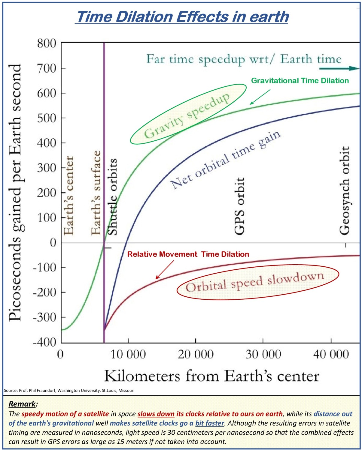
4.3.1. Time dilation
The fundamental frequency of the satellite oscillator is f0 = 10.23 MHz (λ = 29.3 m). From it all frequencies are derived.
When setting the fundamental frequency, it is necessary to incorporate relativistic influences of the special theory of relativity (Albert Einstein, 1905).
For this it is required to consider two types of time dilation:
a) Time dilation by movement tells:
"That all internal processes of a physical system are elapsing slower relative to the observer if this system moves relative to the observer."
What does that mean?
This means that watches that move relative to the observer, go slower than his own. This effect is stronger the greater the relative velocity.
In other words, clocks in fast-moving reference systems are slower than those in stationary reference systems.
In terms of GPS, this means that the clocks in the satellites are slower than the clocks in the receivers on the ground.
b) Gravitative time dilation tells:
"That a watch, like any other process, runs slower in a stronger gravitational field than in a weaker one."
In this way time passes in a distant, approximately gravitational free space faster than on the earth's surface. More precise, everybody opposite to the gravitational field resting observer measures a longer or shorter elapse time of events which are triggered in an identical manner in and out of the gravitational field. Different to time dilation by relative motion, is the gravitational time dilation not mutually. While the upper observer in the gravitational field sees the time of the lower observer goes slower, the lower observer sees the time of the upper observer goes correspondingly faster.
In terms of GPS, this means that the clocks in the satellites go faster than the clocks in the receivers on the ground.
If one summarizes both effects and considers the frequency shift instead of the time offset, the result for the GPS system is that the frequency of the satellite clocks is of the factor 4.5 * 10-10 Hz higher than that of a reference clock on Earth's surface. To compensate for this effect and assume a fundamental frequency of 10.23 MHz, the frequencies of the satellite clocks are set to a value of
f = 10.22999999545 MHz
4.3.2. Phase Modulation
Signals with simple harmonic oscillation hold the danger of
Unwanted third-party-use, due to the free access
Signal ambiguity caused by measurement of phasing position in the range of one wavelength, which doesn't allows a current satellite position for the user.
By phase modulation of the signals, the problems mentioned can be avoided.
To that for f1 and f2 will used so-called pseudo-random sequences, also called pseudo-random noise codes (PRN code).
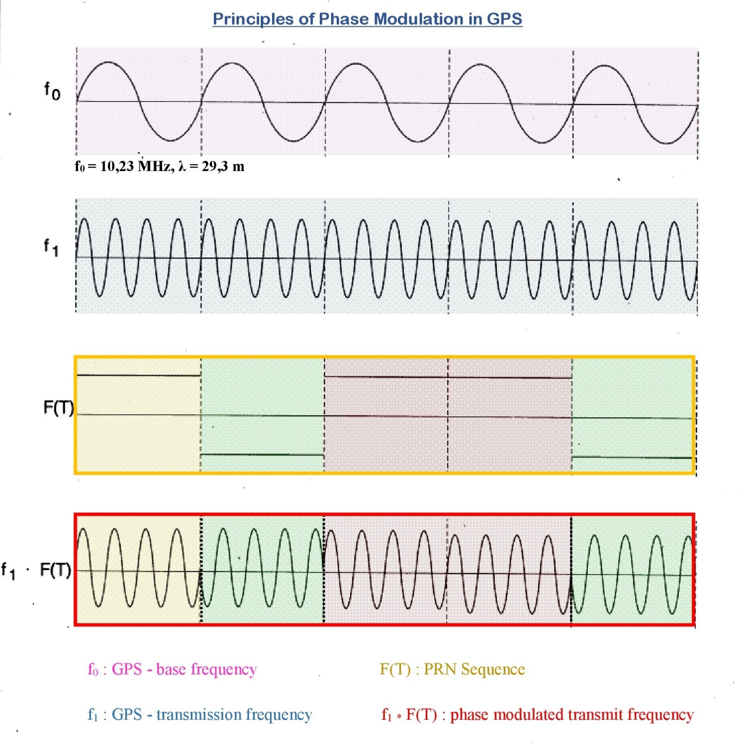
In order to make the signal of a particular satellite recognizable to the receiver and to transmit the navigation message, the signals are modulated in several steps, in which the phases of the carrier frequencies f1 and f2 in accordance with pseudorandom sequences of the values +1 and -1 (PRN Sequences) are changed. For a random sequence, each element takes the values +1 and -1 with the same probability. For a pseudo-random sequence, the sequence of elements will repeat the period of the sequence after a certain time. The values +1 and -1 in the case of the GPS signals are functional values of a stair function of the satellite time T (also known as the Heaviside function, named after the British mathematician and physicist Heaviside, see F(T) in the adjacent diagram) and cause the following:
+1, the signal remains unchanged.
-1 causes a phase shift about 180 °.
In order to be able to exclude interferences of the signals and assign them clearly to the satellite, the selection of the specific PRN sequences takes place so that they do not correlate with each other. At the same time, the frequencies L1 and L2 are coded differently to restrict civilian use. In the following subchapter more.
4.3.3. GPS Signal Coding
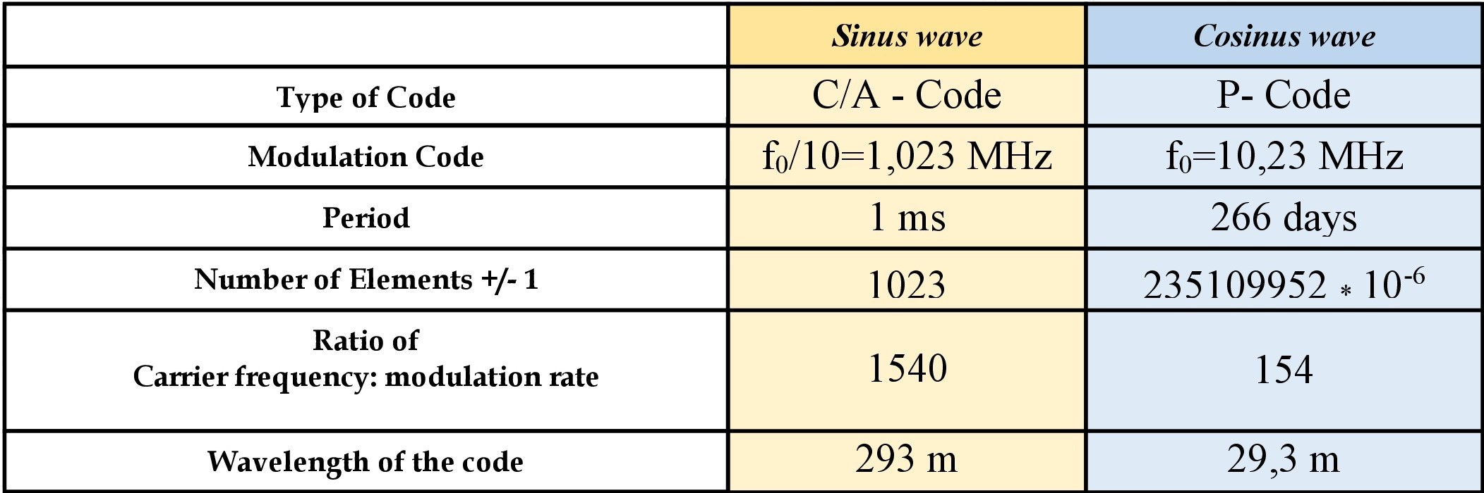
In my explanation, I confine myself to the principle of coding, the signal L1 accessible for civilian use, since the coding procedure for L2 is based on exactly the same principles. With the difference that for L2 only the cosine wave is modulated and the carrier frequency is generated by f1 = 120 * f0.
In order to obtain the carrier frequency f1, it must be derived from the fundamental frequency; f1 = 154 * f0. By phase shift by 90 ° then another carrier is generated, so that a sine wave and a cosine wave of frequency f1 are present. Subsequently, the two waves are modulated differently and the addition of the modulated waves is transmitted.
The modulation clock (modulation code) indicates in which cycle the stair function of the PRN sequence changes or retains its value. The period is the length of the repeating sequence, so that the product of the modulation clock and period is results the number of elements +1 and -1 within a sequence. The ratio carrier frequency to the modulation clock determines how many waves of a wave train are modulated. For example, in the case of the C / A code, this is every 1540th wave. The Multiplication with the wavelength of the L1 signal λ1 = 0.19 m provides the 'wavelength of the code'.
The data code modulation, which is the same for both waves, follows the modulation with the PRN sequences. In order to guarantee real-time satellite positioning, the required parameters and additional information of the satellites must be available. This is achieved by the fact that the signal with a further phase modulation, packs data for a navigation message and transmits with the signal. The message itself is a 30 second sequence of +/- 1 in the 50 Hz cycle.
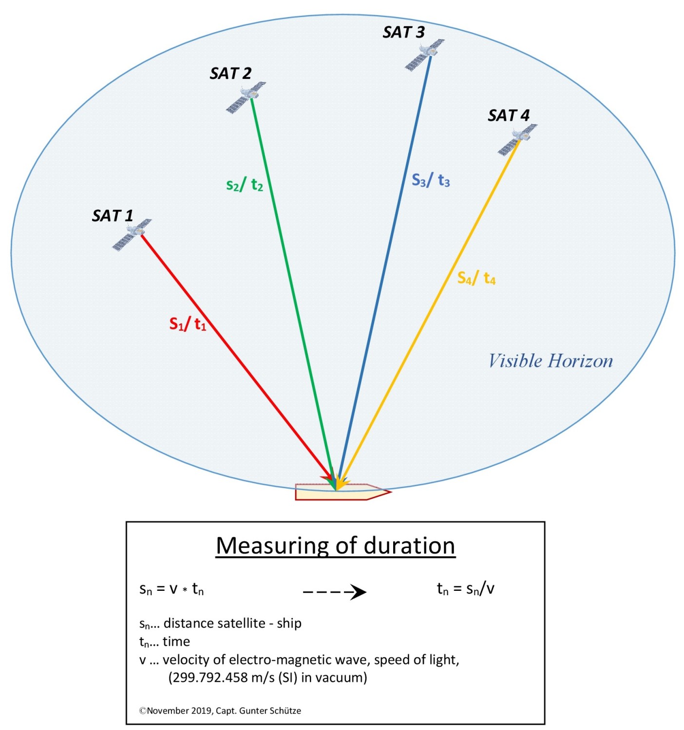
4.3.4. Runtime Measurement
Runtime measurement is a method of indirect distance or velocity measurement by measuring that time which a signal requires to traverse the measuring distance
In this method, the time of a signal emitted by a transmitter is measured until it reaches a known location.
The transit time measurement in GPS is a one-way measurement. In order to obtain a position, signals from several transmitters are required, in the case of GPS, the electromagnetic waves of several satellites (at least 4).
Due to their different distances to a ship, different measured transit time’s result, which are multiplied by the speed of light (c). Their lines converge in the position of the ship. The application of the 4th satellite for transit time measurement serves to determine the receiver watch error.
It is important that the clocks of the transmitters and the ship are synchronized and display the same time. The GPS time is a globally uniform atomic clocked time without a leap second, as opposed to UTC, where this leap second is inserted to keep UTC in agreement with Earth's rotation. Because of this, GPS time and UTC differ, which means GPS time is currently 18 seconds ahead of UTC.
4.4. Position Determination
GPS positioning is based on the signal being received by at least 3 satellites.
It is not based on the true distances to the satellites, but so - called pseudo - distances, which come about as follows:
The modulated signals are used for position determination. Thus, if a satellite is in the range of the GPS receiver, its signal transit time Δt is determined by generating an identical signal and determining the phase shift. By multiplying by the speed of light (c), the pseudo-distance from the satellite can be determined.
It is thereby assumed that the different clocks are not synchronized. Based on the GPS system time, one starts from a reference time, which is the deviations of user time (receiver) to system time (tu) and satellite time to system time (ts). Thus it can be seen that the pseudo-distance is an error caused by time differences, so that
for the actual distance of the user from the satellite is valid.
As the intellectual connection, it should be pointed out that this method of position determination in the broader sense has a similarity with hyperbola radio location procedure.
4.5. Speed Determination
The speed of vessels in the GPS is determined by the Doppler Effect.
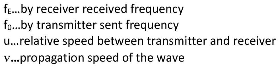
4.5.1. Doppler Effect
The Doppler Effect is named after the Austrian mathematician and physicist Christian Doppler, who in 1842 hypothesized that the colored light of stars is due to their change in distance during light emission. However, this could not be scientifically maintained. However, in 1845 with the commissioning of the railway succeeded in experimental proof of the acoustic Doppler Effect.
The Doppler Effect is based on the change in signal propagation time. It is referred to as the time compression or stretching of a signal with changes in the distance between transmitter and receiver during the duration of the signal. This purely kinematic (resulting from the motion) effect occurs with all signals that propagate at a certain speed, usually the speed of light or the sound velocity. When propagation in a medium, such as water, its state of motion must be considered.
That means nothing else than:
If an object in motion is approaches an object at rest, then the signal waves are compressed, with the effect that the wavelength (λ) is shortened, resulting in a frequency change to higher frequencies (f). Acoustically, it is noticeable that the pitch increases during the approaching phase.
If the moving object passes the resting object and moves away, the opposite occurs. The signal waves are stretched, the wavelength will thus longer and thus the frequency comes lower, which is acoustically in progressively lower tones
These frequency changes are referred to as Doppler frequency shift.
Even if both objects are in motion, this principle forms the basis of the velocity determination, since the same effects occur on approaching and to move away motion, taking into account the motion parameters of both objects, so long the two objects have different motion velocity (the relative speed vector must be > 0).
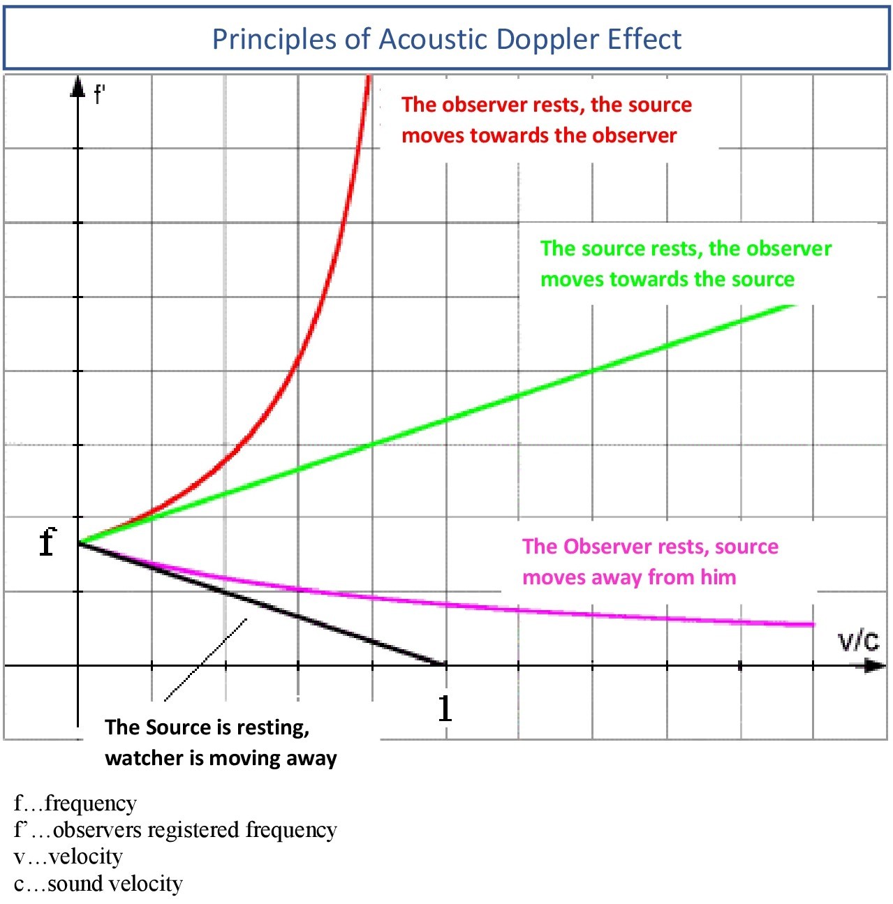
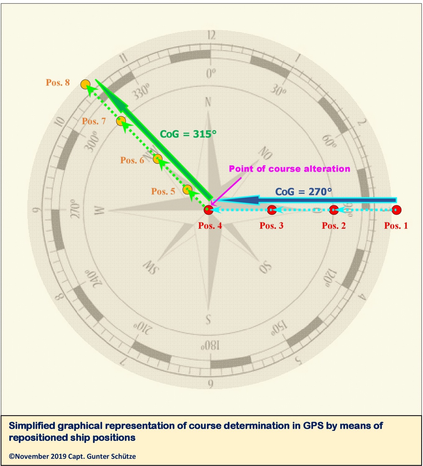
4.6. Course determination in the GPS
The course calculation in the GPS is based on the determination of the distance traveled, that is. It is an analysis of the direction of movement of ship positions in past, which are connected by straight lines whose direction is shown as a two-dimensional course vector in 360 degree representation, north stabilized. In a figurative sense, this can be compared with the radar representation in the "Past Track" mode. The accuracy of the course value is depends from accuracy of the receiver and the time interval of the position determination. To do this, the GPS receiver must be in motion. This also explains why for ships at anchor while turning around the anchor the course and speed determination is jumpy.
The position update is performed every 1 second in the standard procedure and every 0.1 second at the maximum update rate.
4.7. Selected Availability and Anti-Spoofing
A short insight into the possibilities of influencing the accuracy of GPS and preventing spoofing against GPS.
4.7.1. Selective Availability (SA)
he accuracy of GPS available to the user is at the operator's discretion with the Selected Availability (SA) tool. There have been discussions over and over again in the past, because the accuracy differences are considerable. With SA: 100 -150 m and without SA: 5 - 10 m. They are caused by artificial falsification of the satellite orbits and by artificially created receiver noise of the carrier signal. SA was switched off in May 2000. The effects can also be seen in the left graphic.
AS is usable to the L1 and L2 frequency.
4.7.2. Anti-Spoofing (A-S)
Anti-spoofing is established to prevent that transmitted signals can be influenced by false signals and thus will receiving incorrect information from the receivers which limit or even render impossible the function of GPS.
For this purpose, the P-code (Precise Code) is additionally encrypted with a Y-code, referred to as P / Y code. This ensures that for unauthorized users, ie the public, only the C / A coded part (Coarse / Aquisition - Civilian Access Code) of the L1 frequency can be used.
Authorized users of the P / Y code, armed forces and authorized authorities typically have dual frequency receivers that can receive L1 and L2 frequencies that are automatically corrected via a dedicated receive module and operate with high accuracy.
It must always be aware that GPS is a military system under the control of the US Forces. That means that SA and A-S can be activated at any time for the L1 frequency resulting in limited civilian use.
In the past, some regions of the world, e.g. Black Sea and Northern Norway, have reported massive disruptions of GPS usage allegedly due to spoofing attacks. I see these reports critically, as also technical and physical error influences, the function can disturb massively. But more on that later.
5. DGPS (Differential Global Positioning System)
DGPS is a system that also works on the basis of transit time measurement. It is founded on stationary antennas that are installed as reference stations on land. Their position has been determined by classical surveying methods, which ensures a high accuracy of the position. DGPS has the task to correct the existing error inaccuracies of GNSS (Global Navigation Satellite System). DGPS is not limited to GPS, but for GNSS, so all existing satellite navigation systems available.
The method makes use of the fact that the actual signal propagation times can be determined from the deviation of the actual position and the received position. The difference between the theoretical and the actual signal propagation time is transmitted to the DGPS receivers in the respective region. DGPS receivers on board correct this difference and thus increase the accuracy of the position determination. The associated accuracy depends on the distance of the receiver from the reference station on land. Accuracies of approx. 0.5 m to 2.5 m are possible.
It is noteworthy that, in addition to the onshore stationary regional DGPS reference stations, which is only regionally usable, there is also a satellite-based DGPS system, which enables the worldwide use of DGPS.
It is based on geostationary satellites orbiting Earth at 36000 km altitude, always maintaining their same position to Earth. It is referred to as SBAS (Satellite Based Augmentation System) and also serves to increase the accuracy in determining the position of GNSS.
There are currently four systems active and two more systems under construction, but these are currently mainly used in flight navigation.
Epilogue
The purpose of this paper is primarily to provide nautical cadets, students and officers with basic knowledge about GPS as currently the most commonly used satellite navigation system. I have the view that the user must be able to know technical and physical fundamentals. The practice on board has shown that only fragmentary knowledge is available.
I hope this work is a clearly arranged form a way given to navigators’ basic knowledge to hand.
In the second part I will deal more intensively with occurring technical and physical errors, which are unavoidable with GPS as a technical system, which is used on the basis of the wave theory. This should also help to not immediately classify any irregularity in the operation of GPS as a spoofing attack.
© Copyright November 2019, Capt. Gunter Schütze. Replication or redistribution in whole or in part is expressly prohibited without the prior written consent by Capt. M.Eng. Gunter Schütze
, physical and technical errors of GNSS - an error analysis")